ESP8266 minimal I2C board


This was originally designed as a 'giveaway' We wanted something a little more original than mugs, beer mats, ball point pens etc etc...

As with the tiny OLED design, the idea is that this operates from a cheap USB phone charger.

It's unlikely that we would supply these built unless a considerable demand exists so we've decided to make the PCBs available for you to build your own. The design files are not available so please don't ask.

We're not looking to get rich from this but a few quid towards development costs would be nice...

You can buy 6 PCBs for £8 including (European) delivery.


We've discovered that UK postal charges make it very difficult to break even if we sell very small value items.

However, you could easily use six of these on your home network!

Background

The original design aim was to produce a useful IOT device for as little cost as possible. The first prototypes used a DHT11 & ESP01 on a USB stick. It looked very like the board described here.

It worked very well but offered little scope for experimentation. The DHT11 is cheap, cheerful, & robust, but it isn't very good & it isn't I2C :(
I may be the first person to have noticed, but lots of I2C boards are available with a common pinout: Vcc-GND-SCL-SDA

Essentially this is just a carrier board. It uses a cheap 1117 regulator to derive 3v3 from the USB connector. I2C pins are broken out so you can connect whatever you want.

We used this approach in our Wemos experimenter board. The ESP8266 doesn't have a lot of I/O pins but the availability of cheap I2C sensors with a common footprint makes up for this.
The examples for the Wemos experimenter board will work, but you will need to change the I2C pin designations.

Construction


Assemble the components:


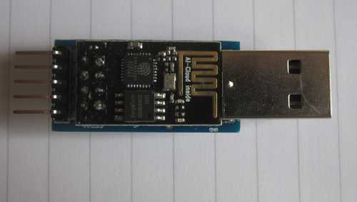
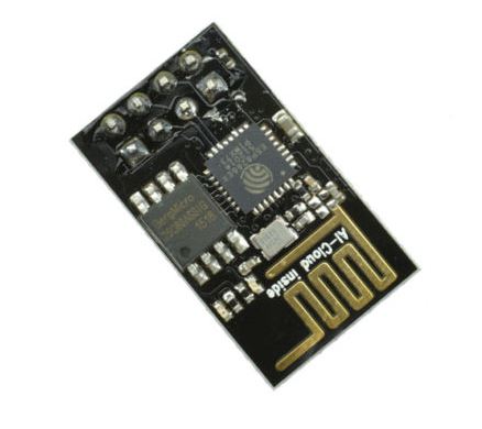
You need a ESP01. Be sure to get a black one as these seem guaranteed to have 1M FLASH


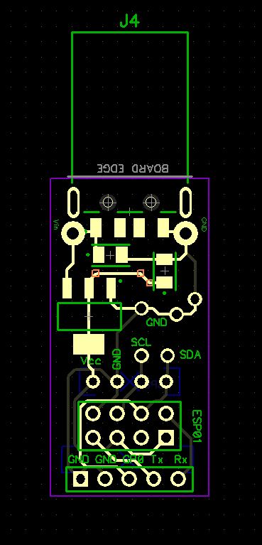
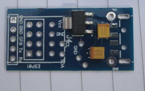
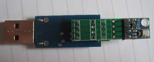
A PCB to hold everything together. If you are sharp eyed you might spot a few unused pads on the PCB - Five to be precise.
These were added to allow(eg) a piezo buzzer to be attached (if you can find one small enough!) instead of using a I2C device.

Another option which has proved surprisingly useful is to connect a white LED between the GND & SCL pins. You don't need any current limiting.


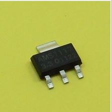
A 1117 3v3 regulator. This drops the incoming 5v from the USB connection to 3v3.


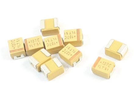
You need two 100uF tantalum capacitors. The footprint is '3528'
These are big enough to solder by hand.


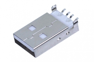
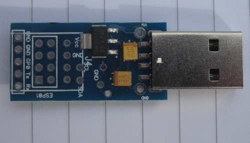
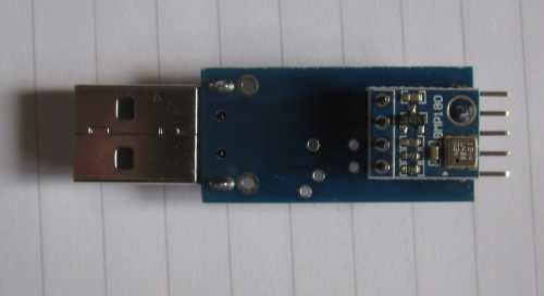
A male USB plug with surface mount tags. This is the power connector.


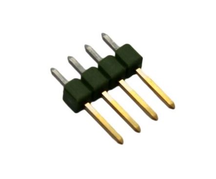
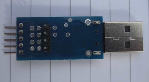
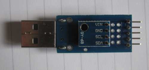
A 4 pin male header connects your I2C device.


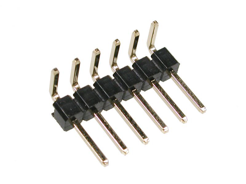
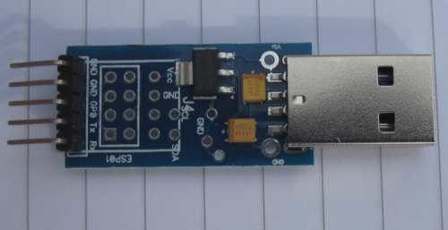
A 5 pin male right-angle header provides the programming interface.
Yes! I know the photo has 6 pins!!

You need a 5 pin header! Hopefully you'll just snap 5 pins from a long header...

Actually, you don't need this at all if you opt for OTA programming...

Putting it all together


These devices need to be built in the correct order but there's nothing tricky.

Assemble the PCB. Attach the voltage regulator and capacitors. These are easily soldered by hand - a handy tip is to hold each component in place with a crocodile clip when you're soldering.

Obviously if you have an oven this step is easy.


Add the USB plug. This should clip into place & is easily soldered. Only the outer two (power) pins need to be soldered, so if fine soldering isn't your thing leave the middle two alone.

Be sure to solder the two lugs on the USB plug. They add significant strength. There are two pads adjacent to the USB plug which can be used to provide power in (if the USB connector isn't used)


Now add the 5 pin programming header.


And the 4 pin male I2C header


Insert the ESP01 & solder it in place.
Although it's not necessary, you might prefer to program your ESP01 before you solder it in place. A simple OTA program is suggested.
You don't need the 5 pin header to use OTA.


Now we are ready for a I2C sensor:


Or perhaps:


If you use a header with long pins you can stack 2 or 3 sensors - it's an I2C bus after all...

Use


Remember the USB connector is only for power.
It was designed this way as USB phone chargers are an incredibly cheap power source!

To program the board serially, you need to apply power to the USB connector. The 5 pin programming connector has GPIO0 and GND on adjacent pins. Linking these pins will put the ESP01 into bootload mode at power up.
Connect a serial adapter to the Tx, Rx, and GND pins as you would normally do.

Unless you are doing something very adventurous, the 1M ESP01 has plenty of memory for OTA programming. Consider doing this as it's a little more convenient.

If memory is a serious issue, it's quite easy to change the 1MB flash on the ESP01 for 16MB & it works very nicely :)

Imortant note about Bosch sensors; we have found that these are very susceptible to being 'warmed' through PCB tracks & may read two or three degrees above ambient. If your application has the ESP01 working hard this may be an issue and you should use an extender board:


The extender board is provided with the PCB.  It has extra pads for extra sensors, and/or it can be easily cut down with a pair of scissors.

Top Tips


Ian Sexton