ESP12 Programming Fixture
Background
The ESP12 is possibly the most widely used of all the ESP8266
modules & with good reason.
It's supported by excellent products such as the Wemos D1 and
NodeMCU boards, to name but two.
It's guaranteed to have 4MBytes of memory which sets it apart from
other boards and this is important.
The ESP8266 has 1MByte of program space. To use Over The Air (OTA)
programming we potentially need another 1MByte to upload a new
image.
We might need to store data in the flash memory too, so 2MB+ is very
useful.
Those of us who have stepped beyond Wemos etc realise that 'in
circuit' programming is a potential issue. Rarely a deal breaker but
something to consider.
The photo below shows a prototype of mine. It uses a ESP12 and has a
dedicated programming connector.
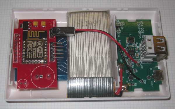
The programming connector comprises: Din, Dout, GND, & GPIO0. OK
there are 5 pins; two are GND so GPIO0 & GND can be linked
easily.
This works fine, but recently I needed to make something
with a very low profile & keep it as small as possible.
Actually this was a favour for a friend.......
Essentially, we needed to program the ESP12 BEFORE it was
soldered to a board.
Solution
There are several programming boards available to do this. Take a
look on Ebay. They are all a little pricey but in general I don't
object to paying for tools I need.
I was in a rush & didn't want to wait weeks for something I
needed NOW.
I had a bag of 'pogo'
pins in my junk box so I thought I'd make something myself...
I have a modest
3D printer which I'm getting better at using so I printed a
jig to hold a ESP12 & a few pogo pins:
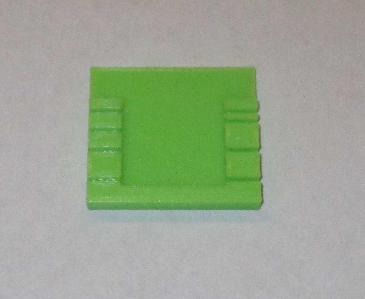
The pins are 1mm diameter and push tightly into the 1mm slots in the
jig.
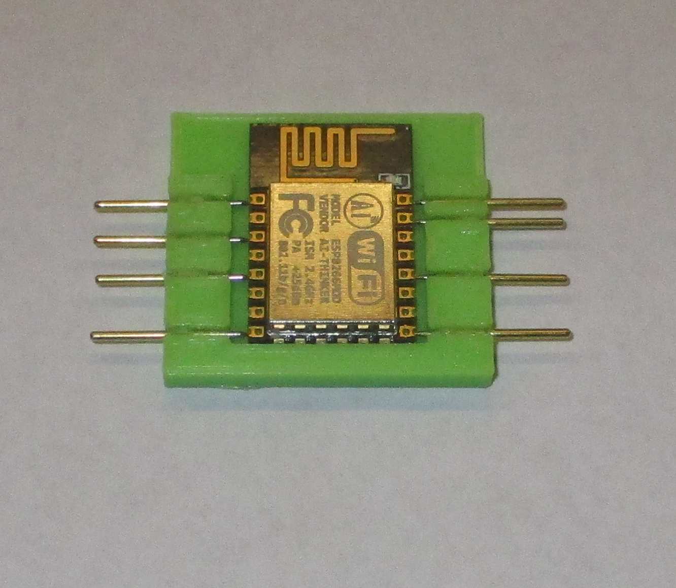
A tiny drop of superglue holds the pins very securely in place. We
don't need 8 pins but I discovered that extra pins are
useful to equalize the force on each side. We actually need four on
the right & one on the left.
Du Pont connectors will push onto the pins (just!) apart from the Rx
& Tx pins (top right in the photo) which are only 2mm apart. We
need to solder leads here.
Soldering leads is very easy anyway as the pins are gold plated.
If you have a 3D printer this is easy to design, make, and probably
improve. My STL file is here if you want a
starting point.
It's quite fiddly to put together. Especially if your eyesight is
like mine! Check it's ok before you add any superglue :)
Finally
A favour for a friend indeed! I'm not sure that this has even been
used & I'm too busy to test it, but at least I'm owed a few
beers!!
I'm not planning to sell these things but if you don't have a 3D
printer & REALLY want one send an email (below).