4 (four) PCBs cost £6 including
international delivery
|
4 (four) PCBs cost £6 including
international delivery
|
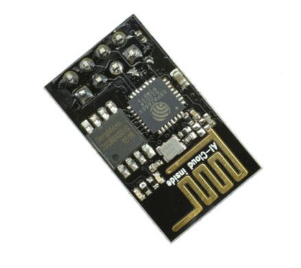 |
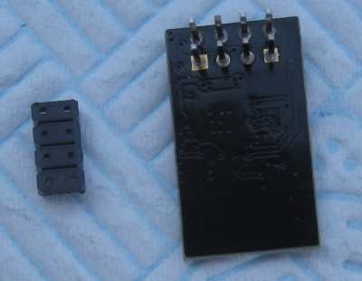
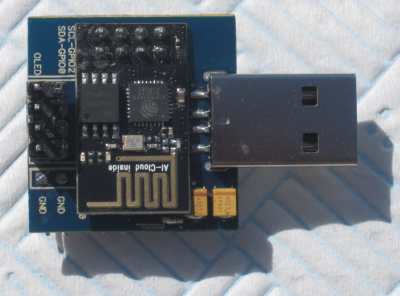
You need a ESP01. Be sure to get a black one as these seem guaranteed to have 1M FLASH |
 |
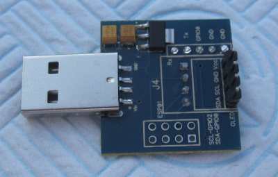
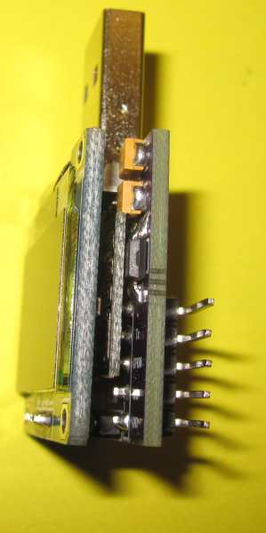
A PCB to hold everything together. Note: in this image (and the first batch of PCBs) the polarity of the capacitors is wrong! These are the two components at top right of the PCB in the photo. This will be more obvious in the assembly instructions. |
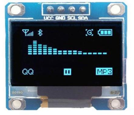 |
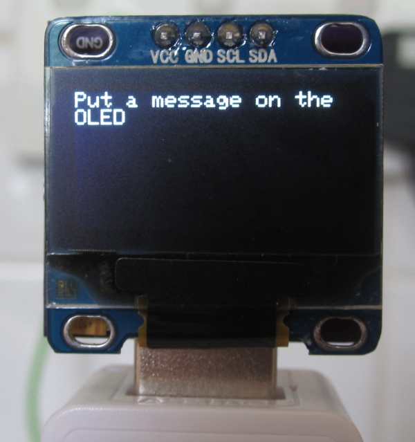
Obviously you need one of these! A SSD1306 I2C OLED display. Be careful to get the right one! Note the pinning: VCC-GND-SCL-SDA Unfortunately there are other displays available where VCC & GND are swapped. |
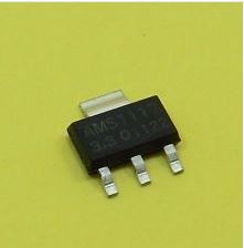 |
A 1117 3v3 regulator. This drops the incoming 5v from the USB connection to 3v3. |
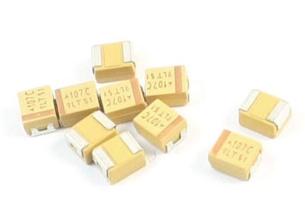 |
You need two 100uF tantalum capacitors. The footprint is '3528' These are big enough to solder by hand. |
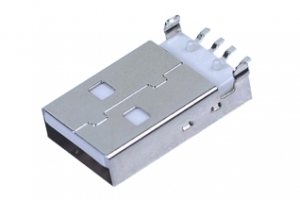 |
A male USB plug with surface mount tags. This is the power connector. |
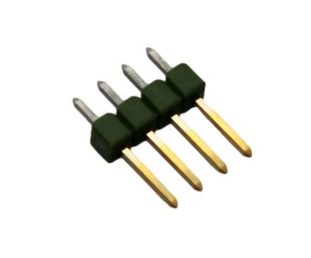 |
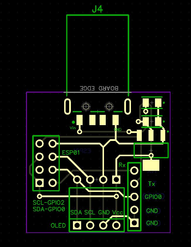
A 4 pin male header connects the PCB to the OLED display. |
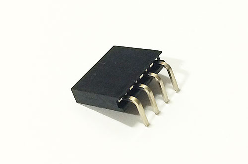 |
A 4 pin female right-angle header allows attachment of other I2C devices; BME280 etc etc |
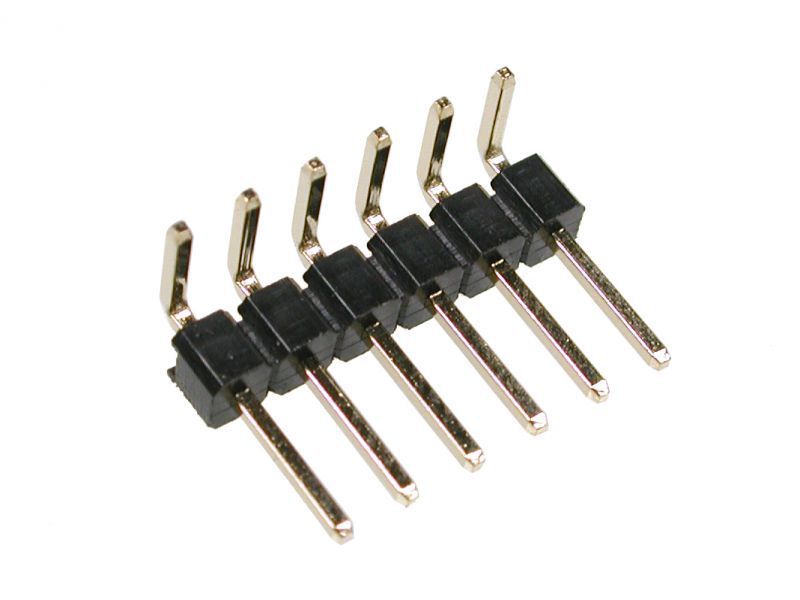 |
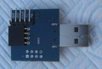
A 5 pin male right-angle header provides the programming interface. Yes! I know the photo has 6 pins!! You need a 5 pin header! Hopefully you'll just snap 5 pins from a long header... |