|
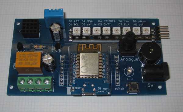
Built & tested INCLUDING Wemos D1 mini: £25 |
Blank PCB - you will receive 2 (TWO) PCBs : £10 |
In the beginning - BlinkNode-Red 1
Testing the relay
Fade the LED
Test the switch
Test the switch with interupts
Another switch?
Analogue input
I2C
I2C scannerDHT11 temperature & humidity
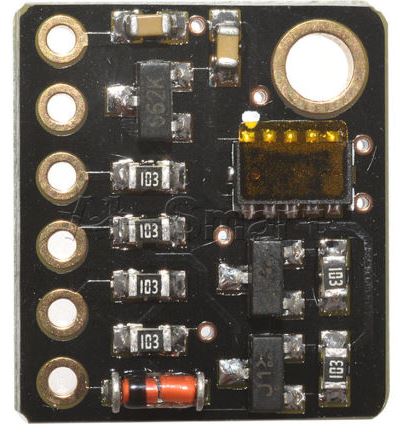
BMP180 Pressure/temperature
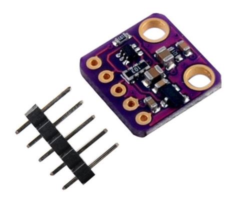
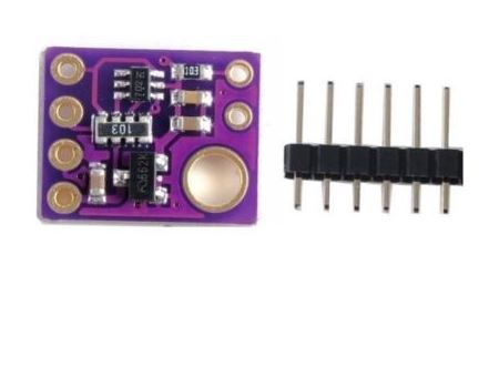
BME280 Pressure/temperature/humidity
BH1750 Lux sensor
VEML6070 UV sensor
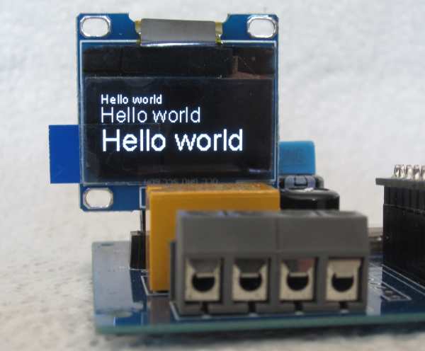
OLED
VL53L0X LIDAR
APDS9960 gesture sensor
SI1145 UV index sensor
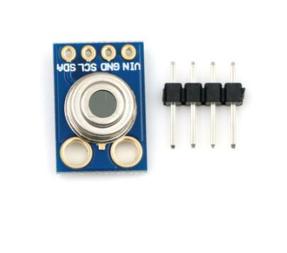
MLX90614 temperature (non contact)
Using D1 & D2 I2C pins
One-Wire DS18B20 Temperature sensor
Neopixel - WS2812 RGB LEDs
Piezo Buzzer
WiFi
A Webserver (AP mode)
Connecting to an existing WiFi network (STA mode)
A Webserver (STA mode)
SPIFFS
A real webserver
OTA programming
Sleep
MQTT
#define LED 16
or
#define LED D0
//Blink Turns on an LED on for one second, then off for one second, repeatedly.

#define LED D0    //white LED is on D0
void setup() {
  pinMode(LED, OUTPUT);  // initialize LED pin as an output.
}

void loop() {
  digitalWrite(LED, !digitalRead(LED)); //toggle the LED
  delay(1000);                       // wait for a second
}
#define RELAY D7
void setup() {
  pinMode(RELAY, OUTPUT);
}

void loop() {
  digitalWrite(RELAY, !digitalRead(RELAY));   // toggle relay
  delay(1000);                       // wait for a second
}
/*
 Fade

 This example shows how to fade an LED
 using the analogWrite() function.

 The analogWrite() function uses PWM.
 Available values are 0-1023 (ie 10 bits)
 This example code is in the public domain.
 */
#define LED D0
int brightness = 0;    // how bright the LED is to start with
int fadeAmount = 5;    // how many points to fade the LED by

void setup() {
  // declare pin to be an output:
  pinMode(LED, OUTPUT);
}

// the loop routine runs over and over again forever:
void loop() {
  analogWrite(LED, brightness);  // set the brightness

  // change the brightness for next time through the loop:
  brightness = brightness + fadeAmount;

  // reverse the direction of the fading at the ends of the fade:
  if (brightness <= 0 || brightness >= 1023) {
    fadeAmount = -fadeAmount;
  }
  // wait to see the dimming effect
  delay(10);
}
Now we are getting clever! Inputs and outputs together. Let's reflect the status of the switch on the LED. When you press the button the LED is off & vice versa.
See if you can make it work the other way around. The switch
input is normally high & goes low when we press the button.
The LED is anode driven, ie a '1' lights it.
#define LED D0
#define SWITCH D3

void setup() {
  pinMode(LED,OUTPUT);
  pinMode(SWITCH,INPUT);
}

void loop() {
  digitalWrite(LED,digitalRead(SWITCH));  //reflect switch status on LED
}
// This program demonstrates interrupts. A push button switch generates an interrupt.
// The interrupt is used to toggle the state of a LED
// It doesn't always work perfectly - a neat demo of 'switch bounce'

#define LED D0
#define SWITCH D3

volatile byte state = LOW;  //volatile = tell the compiler that this is changed by an interrupt

void setup() {
  pinMode(LED, OUTPUT);
  pinMode(SWITCH, INPUT_PULLUP);
  attachInterrupt(digitalPinToInterrupt(SWITCH), blink, FALLING);
  Serial.begin(115200);
}

void loop() {
  digitalWrite(LED, state);
  Serial.println(state);
  delay(200);
}

void blink() {    //the ISR - good practice to keep it as brief as possible
  state = !state;
}
There is a potentiometer on the board. Here we use it to control
the brightness of the LED. The program is slightly tweaked. The
A/D converter returns a 10 bit value (ie 0-1023) however, in
practice, values below around 7 are rarely achieved with our
circuit.
There is no provision for an external analogue input on the board.
#define LED D0
#define POT A0

void setup() {
  Serial.begin(115200);
}

void loop() {
  int x = analogRead(POT);
  Serial.println(x);
  if (x < 9)    //can't get down to zero with circuit as is
    x = 0;
  analogWrite(LED, x);    //control white LED brightness
  delay(100);             //just for the print
}
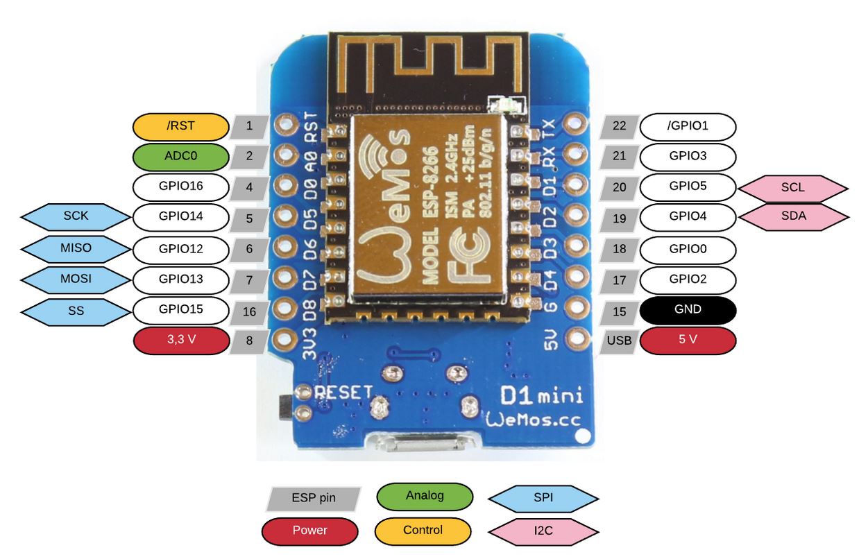
The ESP8266 uses software driven I2C which is managed by the 'Wire' library. Any pins can be used for I2C but we have followed the Wemos convention & used their default pins, D1=SCL & D2=SDA.
If you are not using the I2C bus, D1 & D2 are available for other use as General Purpose I/O. You might (for example) attach an ultrasonic rangefinder to these pins.
A shortcoming of the ESP8266 is its lack of I/O pins but this
isn't usually a show stopper. If you are desperate for more I/O
you might consider a I2C port expander.
#include <Wire.h>

void setup()
{
  Wire.begin();
  Serial.begin(115200);
  Serial.println("\r\nI2C Scanner");
}
void loop()
{
  byte error, address;
  int nDevices;
  Serial.println("Scanning...");
  nDevices = 0;
  for (address = 1; address < 127; address++ )
  {
    // The i2c_scanner uses the return value of
    // the Write.endTransmisstion to see if
    // a device did acknowledge to the address.
    Wire.beginTransmission(address);
    error = Wire.endTransmission();

    if (error == 0)
    {
      Serial.print("I2C device found at address 0x");
      if (address < 16)
        Serial.print("0");
      Serial.print(address, HEX);
      Serial.println("  !");

      nDevices++;
    }
    else if (error == 4)
    {
      Serial.print("Unknow error at address 0x");
      if (address < 16)
        Serial.print("0");
      Serial.println(address, HEX);
    }
  }
  if (nDevices == 0)
    Serial.println("No I2C devices found\n");
  else
    Serial.println("done\n");

  delay(5000);           // wait 5 seconds for next scan
}
#include <Wire.h>
#include <Adafruit_Sensor.h>
#include <Adafruit_BMP085_U.h>

/* This driver uses the Adafruit unified sensor library (Adafruit_Sensor),
   which provides a common 'type' for sensor data and some helper functions.

   THIS SEEMS TO WORK

   To use this driver you will also need to download the Adafruit_Sensor
   library and include it in your libraries folder.

   You should also assign a unique ID to this sensor for use with
   the Adafruit Sensor API so that you can identify this particular
   sensor in any data logs, etc.  To assign a unique ID, simply
   provide an appropriate value in the constructor below (12345
   is used by default in this example).

   Connections
   ===========
   Connect SCL to analog 5
   Connect SDA to analog 4
   Connect VDD to 3.3V DC
   Connect GROUND to common ground

   History
   =======
   2013/JUN/17  - Updated altitude calculations (KTOWN)
   2013/FEB/13  - First version (KTOWN)
*/

Adafruit_BMP085_Unified bmp = Adafruit_BMP085_Unified(12345);

/**************************************************************************/
/*
    Displays some basic information on this sensor from the unified
    sensor API sensor_t type (see Adafruit_Sensor for more information)
*/
/**************************************************************************/
void displaySensorDetails(void)
{
  sensor_t sensor;
  bmp.getSensor(&sensor);
  Serial.println("------------------------------------");
  Serial.print  ("Sensor:       "); Serial.println(sensor.name);
  Serial.print  ("Driver Ver:   "); Serial.println(sensor.version);
  Serial.print  ("Unique ID:    "); Serial.println(sensor.sensor_id);
  Serial.print  ("Max Value:    "); Serial.print(sensor.max_value); Serial.println(" hPa");
  Serial.print  ("Min Value:    "); Serial.print(sensor.min_value); Serial.println(" hPa");
  Serial.print  ("Resolution:   "); Serial.print(sensor.resolution); Serial.println(" hPa");
  Serial.println("------------------------------------");
  Serial.println("");
  delay(500);
}

/**************************************************************************/
/*
    Arduino setup function (automatically called at startup)
*/
/**************************************************************************/
void setup(void)
{
  Serial.begin(115200);
  Serial.println("Pressure Sensor Test"); Serial.println("");

  /* Initialise the sensor */
  if(!bmp.begin())
  {
    /* There was a problem detecting the BMP085 ... check your connections */
    Serial.print("Ooops, no BMP085 detected ... Check your wiring or I2C ADDR!");
    while(1);
  }

  /* Display some basic information on this sensor */
  displaySensorDetails();
}

/**************************************************************************/
/*
    Arduino loop function, called once 'setup' is complete (your own code
    should go here)
*/
/**************************************************************************/
void loop(void)
{
  /* Get a new sensor event */
  sensors_event_t event;
  bmp.getEvent(&event);

  /* Display the results (barometric pressure is measure in hPa) */
  if (event.pressure)
  {
    /* Display atmospheric pressue in hPa */
    Serial.print("Pressure:    ");
    Serial.print(event.pressure);
    Serial.println(" hPa");

    /* Calculating altitude with reasonable accuracy requires pressure    *
     * sea level pressure for your position at the moment the data is     *
     * converted, as well as the ambient temperature in degress           *
     * celcius.  If you don't have these values, a 'generic' value of     *
     * 1013.25 hPa can be used (defined as SENSORS_PRESSURE_SEALEVELHPA   *
     * in sensors.h), but this isn't ideal and will give variable         *
     * results from one day to the next.                                  *
     *                                                                    *
     * You can usually find the current SLP value by looking at weather   *
     * websites or from environmental information centers near any major  *
     * airport.                                                           *
     *                                                                    *
     * For example, for Paris, France you can check the current mean      *
     * pressure and sea level at: http://bit.ly/16Au8ol                   */

    /* First we get the current temperature from the BMP085 */
    float temperature;
    bmp.getTemperature(&temperature);
    Serial.print("Temperature: ");
    Serial.print(temperature);
    Serial.println(" C");

    /* Then convert the atmospheric pressure, and SLP to altitude         */
    /* Update this next line with the current SLP for better results      */
    float seaLevelPressure = SENSORS_PRESSURE_SEALEVELHPA;
    Serial.print("Altitude:    ");
    Serial.print(bmp.pressureToAltitude(seaLevelPressure,
                                        event.pressure));
    Serial.println(" m");
    Serial.println("");
  }
  else
  {
    Serial.println("Sensor error");
  }
  delay(1000);
}
An interesting point to note about this program is that it was clearly not written with the ESP8266 in mind. Take a close look at the setup() function.
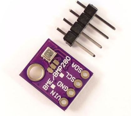
The BME280 is a wonderful device. Unfortunately it's significantly more expensive than (eg) the BMP180, but it's the only single device I know of which offers temperature, pressure, and humidity.
Once again. This is an Adafruit example program. An annoying feature of their examples is that the I2C address of the device is specified in the library files rather than in the main program.
The example also has provision for using the SPI interface which
is irrelevant here. We are strictly I2C.
/***************************************************************************
  This is a library for the BME280 humidity, temperature & pressure sensor

  Designed specifically to work with the Adafruit BME280 Breakout
  ----> http://www.adafruit.com/products/2650

  These sensors use I2C or SPI to communicate, 2 or 4 pins are required
  to interface. The device's I2C address is either 0x76 or 0x77.

  Adafruit invests time and resources providing this open source code,
  please support Adafruit andopen-source hardware by purchasing products
  from Adafruit!

  Written by Limor Fried & Kevin Townsend for Adafruit Industries.
  BSD license, all text above must be included in any redistribution
 ***************************************************************************/

#include <Wire.h>
#include <SPI.h>
#include <Adafruit_Sensor.h>
#include <Adafruit_BME280.h>

#define BME_SCK 13
#define BME_MISO 12
#define BME_MOSI 11
#define BME_CS 10

#define SEALEVELPRESSURE_HPA (1013.25)

Adafruit_BME280 bme; // I2C
//Adafruit_BME280 bme(BME_CS); // hardware SPI
//Adafruit_BME280 bme(BME_CS, BME_MOSI, BME_MISO, BME_SCK); // software SPI

unsigned long delayTime;

void setup() {
    Serial.begin(115200);
    Serial.println(F("BME280 test"));

    bool status;

    // default settings
    status = bme.begin();
    if (!status) {
        Serial.println("Could not find a valid BME280 sensor, check wiring!");
        while (1);
    }

    Serial.println("-- Default Test --");
    delayTime = 1000;

    Serial.println();

    delay(100); // let sensor boot up
}


void loop() {
    printValues();
    delay(delayTime);
}


void printValues() {
    Serial.print("Temperature = ");
    Serial.print(bme.readTemperature());
    Serial.println(" *C");

    Serial.print("Pressure = ");

    Serial.print(bme.readPressure() / 100.0F);
    Serial.println(" hPa");

    Serial.print("Approx. Altitude = ");
    Serial.print(bme.readAltitude(SEALEVELPRESSURE_HPA));
    Serial.println(" m");

    Serial.print("Humidity = ");
    Serial.print(bme.readHumidity());
    Serial.println(" %");

    Serial.println();


}
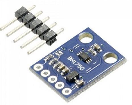
Not a lot we can say about this. The BH1750 is a light level
sensor. It works extremely well!
#include <BH1750FVI.h>

BH1750FVI LightSensor;

void setup()
{
  Wire.begin();
  Serial.begin(115200);
  LightSensor.begin();
  LightSensor.SetAddress(Device_Address_L);//Address 0x23 - in library?
  LightSensor.SetMode(Continuous_H_resolution_Mode);
  Serial.println("\r\nRunning...");
}

void loop()
{
  uint16_t lux = LightSensor.GetLightIntensity();// Get Lux value
  Serial.print("Light: ");
  Serial.print(lux);
  Serial.println(" lux");
  delay(1000);
}
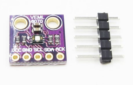
Not a lot we can say about this either. The VEML6070 is a UV light level sensor. It works extremely well too!
It has the same footprint as the other I2C devices illustrated here - we don't use the 'ACK' pin.
The Adafruit library is used & this example is bundled with their library.
#include <Wire.h>
#include "Adafruit_VEML6070.h"

Adafruit_VEML6070 uv = Adafruit_VEML6070();

void setup() {
  Serial.begin(115200);
  Serial.println("VEML6070 Test");
  uv.begin(VEML6070_1_T);  // pass in the integration time constant
}


void loop() {
  Serial.print("UV light level: "); Serial.println(uv.readUV());
  delay(1000);
}
/**
 * The MIT License (MIT)
 *
 * Copyright (c) 2016 by Daniel Eichhorn
 * see https://github.com/squix78/esp8266-oled-ssd1306/tree/master/examples
 * Permission is hereby granted, free of charge, to any person obtaining a copy
 * of this software and associated documentation files (the "Software"), to deal
 * in the Software without restriction, including without limitation the rights
 * to use, copy, modify, merge, publish, distribute, sublicense, and/or sell
 * copies of the Software, and to permit persons to whom the Software is
 * furnished to do so, subject to the following conditions:
 *
 * The above copyright notice and this permission notice shall be included in all
 * copies or substantial portions of the Software.
 *
 * THE SOFTWARE IS PROVIDED "AS IS", WITHOUT WARRANTY OF ANY KIND, EXPRESS OR
 * IMPLIED, INCLUDING BUT NOT LIMITED TO THE WARRANTIES OF MERCHANTABILITY,
 * FITNESS FOR A PARTICULAR PURPOSE AND NONINFRINGEMENT. IN NO EVENT SHALL THE
 * AUTHORS OR COPYRIGHT HOLDERS BE LIABLE FOR ANY CLAIM, DAMAGES OR OTHER
 * LIABILITY, WHETHER IN AN ACTION OF CONTRACT, TORT OR OTHERWISE, ARISING FROM,
 * OUT OF OR IN CONNECTION WITH THE SOFTWARE OR THE USE OR OTHER DEALINGS IN THE
 * SOFTWARE.
 *
 */

// Include the correct display library
// For a connection via I2C using Wire include
#include <Wire.h>  // Only needed for Arduino 1.6.5 and earlier
#include "SSD1306.h" // alias for `#include "SSD1306Wire.h"`
// or #include "SH1106.h" alis for `#include "SH1106Wire.h"`
// For a connection via I2C using brzo_i2c (must be installed) include
// #include <brzo_i2c.h> // Only needed for Arduino 1.6.5 and earlier
// #include "SSD1306Brzo.h"
// #include "SH1106Brzo.h"
// For a connection via SPI include
// #include <SPI.h> // Only needed for Arduino 1.6.5 and earlier
// #include "SSD1306Spi.h"
// #include "SH1106SPi.h"

// Include custom images
#include "images.h"

// Initialize the OLED display using SPI
// D5 -> CLK
// D7 -> MOSI (DOUT)
// D0 -> RES
// D2 -> DC
// D8 -> CS
// SSD1306Spi        display(D0, D2, D8);
// or
// SH1106Spi         display(D0, D2);

// Initialize the OLED display using brzo_i2c
// D3 -> SDA
// D5 -> SCL
// SSD1306Brzo display(0x3c, D3, D5);
// or
// SH1106Brzo  display(0x3c, D3, D5);

// Initialize the OLED display using Wire library
SSD1306  display(0x3c, D2, D1);
// SH1106 display(0x3c, D3, D5);


#define DEMO_DURATION 3000
typedef void (*Demo)(void);

int demoMode = 0;
int counter = 1;

void setup() {
  Serial.begin(115200);
  Serial.println();
  Serial.println();


  // Initialising the UI will init the display too.
  display.init();

 // display.flipScreenVertically();
  display.setFont(ArialMT_Plain_10);

}

void drawFontFaceDemo() {
    // Font Demo1
    // create more fonts at http://oleddisplay.squix.ch/
    display.setTextAlignment(TEXT_ALIGN_LEFT);
    display.setFont(ArialMT_Plain_10);
    display.drawString(0, 0, "Hello world");
    display.setFont(ArialMT_Plain_16);
    display.drawString(0, 10, "Hello world");
    display.setFont(ArialMT_Plain_24);
    display.drawString(0, 26, "Hello world");
}

void drawTextFlowDemo() {
    display.setFont(ArialMT_Plain_10);
    display.setTextAlignment(TEXT_ALIGN_LEFT);
    display.drawStringMaxWidth(0, 0, 128,
      "Lorem ipsum\n dolor sit amet, consetetur sadipscing elitr, sed diam nonumy eirmod tempor invidunt ut labore." );
}

void drawTextAlignmentDemo() {
    // Text alignment demo
  display.setFont(ArialMT_Plain_10);

  // The coordinates define the left starting point of the text
  display.setTextAlignment(TEXT_ALIGN_LEFT);
  display.drawString(0, 10, "Left aligned (0,10)");

  // The coordinates define the center of the text
  display.setTextAlignment(TEXT_ALIGN_CENTER);
  display.drawString(64, 22, "Center aligned (64,22)");

  // The coordinates define the right end of the text
  display.setTextAlignment(TEXT_ALIGN_RIGHT);
  display.drawString(128, 33, "Right aligned (128,33)");
}

void drawRectDemo() {
      // Draw a pixel at given position
    for (int i = 0; i < 10; i++) {
      display.setPixel(i, i);
      display.setPixel(10 - i, i);
    }
    display.drawRect(12, 12, 20, 20);

    // Fill the rectangle
    display.fillRect(14, 14, 17, 17);

    // Draw a line horizontally
    display.drawHorizontalLine(0, 40, 20);

    // Draw a line horizontally
    display.drawVerticalLine(40, 0, 20);
}

void drawCircleDemo() {
  for (int i=1; i < 8; i++) {
    display.setColor(WHITE);
    display.drawCircle(32, 32, i*3);
    if (i % 2 == 0) {
      display.setColor(BLACK);
    }
    display.fillCircle(96, 32, 32 - i* 3);
  }
}

void drawProgressBarDemo() {
  int progress = (counter / 5) % 100;
  // draw the progress bar
  display.drawProgressBar(0, 32, 120, 10, progress);

  // draw the percentage as String
  display.setTextAlignment(TEXT_ALIGN_CENTER);
  display.drawString(64, 15, String(progress) + "%");
}

void drawImageDemo() {
    // see http://blog.squix.org/2015/05/esp8266-nodemcu-how-to-create-xbm.html
    // on how to create xbm files
    display.drawXbm(34, 14, WiFi_Logo_width, WiFi_Logo_height, WiFi_Logo_bits);
}

Demo demos[] = {drawFontFaceDemo, drawTextFlowDemo, drawTextAlignmentDemo, drawRectDemo, drawCircleDemo, drawProgressBarDemo, drawImageDemo};
int demoLength = (sizeof(demos) / sizeof(Demo));
long timeSinceLastModeSwitch = 0;

void loop() {
  // clear the display
  display.clear();
  // draw the current demo method
  demos[demoMode]();

  display.setTextAlignment(TEXT_ALIGN_RIGHT);
  display.drawString(10, 128, String(millis()));
  // write the buffer to the display
  display.display();

  if (millis() - timeSinceLastModeSwitch > DEMO_DURATION) {
    demoMode = (demoMode + 1)  % demoLength;
    timeSinceLastModeSwitch = millis();
  }
  counter++;
  delay(10);
}
#include "Adafruit_VL53L0X.h"

Adafruit_VL53L0X lox = Adafruit_VL53L0X();

void setup() {
  Serial.begin(115200);

  // wait until serial port opens for native USB devices
  while (! Serial) {
    delay(1);
  }

  Serial.println("Adafruit VL53L0X test");
  if (!lox.begin()) {
    Serial.println(F("Failed to boot VL53L0X"));
    while(1);
  }
  // power
  Serial.println(F("VL53L0X API Simple Ranging example\n\n"));
}


void loop() {
  VL53L0X_RangingMeasurementData_t measure;

  Serial.print("Reading a measurement... ");
  lox.rangingTest(&measure, false); // pass in 'true' to get debug data printout!

  if (measure.RangeStatus != 4) {  // phase failures have incorrect data
    Serial.print("Distance (mm): "); Serial.println(measure.RangeMilliMeter);
  } else {
    Serial.println(" out of range ");
  }

  delay(100);
}
This device isn't quite as clever as it sounds. It estimates a 'UV index' from measured visible and IR light. It does not detect UV light.
See the VEML6070 above for detecting UV light.
Once again, the Adafruit library can be used with this device.
xxxxxxxxxxxxxxxxxxxxxxxxxxxxxxxxxxxxxxxxxxxxxxxxxxxxxxxxxxxxxxxxxxxxxxxxxxxxxxxxxxxxxxxxxxxxxxxxxxxxxxxxxxxxxxxxxxxxxxxxxxxxxxxxxxxxxxxxxxxxxxxxxxxxxxxxxxxxxxxxxxxxxxxxxxxxxxxxxxxxxxxx
Another catchy name! The Melexis MLX90614 is a 'non contact' temperature sensor. It's the kind of thing used in 'gun' type thermometers. Point the gun at the object you want to know the temperature of.
This is a fairly expensive device given that the guns can be purchased very cheaply nowadays so we're not entirely sure why anyone would use this.
Although I suppose the same could be said for any temperature measuring device.
The code uses the Adafruit library without modification.
An alternative library is also available from Sparkfun.
/***************************************************
  This is a library example for the MLX90614 Temp Sensor

  Designed specifically to work with the MLX90614 sensors in the
  adafruit shop
  ----> https://www.adafruit.com/products/1747 3V version
  ----> https://www.adafruit.com/products/1748 5V version

  These sensors use I2C to communicate, 2 pins are required to
  interface
  Adafruit invests time and resources providing this open source code,
  please support Adafruit and open-source hardware by purchasing
  products from Adafruit!

  Written by Limor Fried/Ladyada for Adafruit Industries.
  BSD license, all text above must be included in any redistribution
 ****************************************************/

#include <Wire.h>
#include <Adafruit_MLX90614.h>

Adafruit_MLX90614 mlx = Adafruit_MLX90614();

void setup() {
  Serial.begin(115200);

  Serial.println("Adafruit MLX90614 test");

  mlx.begin();
}

void loop() {
  Serial.print("Ambient = "); Serial.print(mlx.readAmbientTempC());
  Serial.print("*C\tObject = "); Serial.print(mlx.readObjectTempC()); Serial.println("*C");
  Serial.print("Ambient = "); Serial.print(mlx.readAmbientTempF());
  Serial.print("*F\tObject = "); Serial.print(mlx.readObjectTempF()); Serial.println("*F");

  Serial.println();
  delay(500);
}
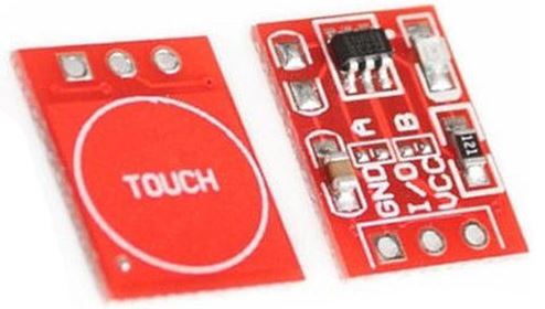
// Using the I2C pins (D1 & D2)
// Although we would normally use D1 & D2 for I2C they are not dedicated to this function
// The program below demonstrates the use of these pins with a cheap touch switch.
// The touch switch has 3 pins: GND,DATA,Vcc
// Unfortunately the pins don't match our sockets so I've connected GND-GND, DATA-D1, Vcc-D2
// By outputting '1' on D2 we power the switch (it needs a couple of mA so we're ok to do this)
// The switch is based on the TTP223 IC & is very popular (and cheap) on ebay.

#define DATA D1
#define VCC D2

void setup() {
  Serial.begin(115200);
  pinMode(DATA, INPUT);     //usually used for SCL
  pinMode(VCC, OUTPUT);     //usually used for SDA
  digitalWrite(VCC, 1);     //provides power to the touch switch

}

void loop() {
  Serial.println(digitalRead(DATA));
  delay(100);
}
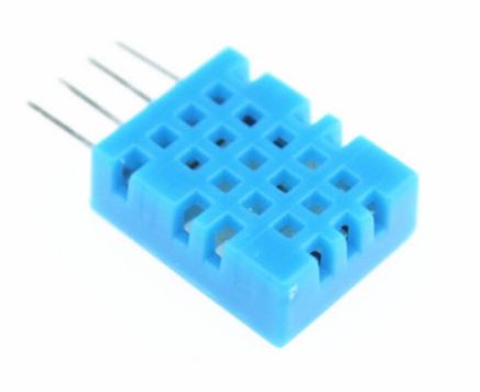
// Example testing sketch for DHT11 humidity/temperature sensor
// Original code written by ladyada, public domain

#include "DHT.h"    //adafruit library
#define DHT_PIN D5
#define DHTTYPE DHT11   // DHT 11

DHT dht(DHT_PIN, DHTTYPE);  // Initialize DHT sensor.

void setup() {
  Serial.begin(115200);
  Serial.println("\r\nDHT11 test");
  dht.begin();
}

void loop() {
  delay(3000);  // Wait a few seconds between measurements.

  float h = dht.readHumidity();
  float t = dht.readTemperature();  // Read temperature as Celsius (the default)

  // Check if any reads failed and exit early (to try again).
  if (isnan(h) || isnan(t)) {
    Serial.println("Failed to read from DHT sensor!");
    return;
  }

  Serial.print("Humidity: ");
  Serial.print(h);
  Serial.print(" %\t");
  Serial.print("Temperature: ");
  Serial.print(t);
  Serial.println(" *C ");

}
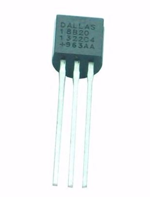
#include <OneWire.h>

// OneWire DS18S20, DS18B20, DS1822 Temperature Example
//
// http://www.pjrc.com/teensy/td_libs_OneWire.html
//
// The DallasTemperature library can do all this work for you!
// http://milesburton.com/Dallas_Temperature_Control_Library

OneWire  ds(D4);  // on pin 10 (a 4.7K resistor is necessary)

void setup(void) {
  Serial.begin(115200);
}

void loop(void) {
  byte i;
  byte present = 0;
  byte type_s;
  byte data[12];
  byte addr[8];
  float celsius, fahrenheit;

  if ( !ds.search(addr)) {
    Serial.println("No more addresses.");
    Serial.println();
    ds.reset_search();
    delay(250);
    return;
  }

  Serial.print("ROM =");
  for( i = 0; i < 8; i++) {
    Serial.write(' ');
    Serial.print(addr[i], HEX);
  }

  if (OneWire::crc8(addr, 7) != addr[7]) {
      Serial.println("CRC is not valid!");
      return;
  }
  Serial.println();

  // the first ROM byte indicates which chip
  switch (addr[0]) {
    case 0x10:
      Serial.println("  Chip = DS18S20");  // or old DS1820
      type_s = 1;
      break;
    case 0x28:
      Serial.println("  Chip = DS18B20");
      type_s = 0;
      break;
    case 0x22:
      Serial.println("  Chip = DS1822");
      type_s = 0;
      break;
    default:
      Serial.println("Device is not a DS18x20 family device.");
      return;
  }

  ds.reset();
  ds.select(addr);
  ds.write(0x44, 1);        // start conversion, with parasite power on at the end

  delay(2000);     // maybe 750ms is enough, maybe not
  // we might do a ds.depower() here, but the reset will take care of it.

  present = ds.reset();
  ds.select(addr);
  ds.write(0xBE);         // Read Scratchpad

  Serial.print("  Data = ");
  Serial.print(present, HEX);
  Serial.print(" ");
  for ( i = 0; i < 9; i++) {           // we need 9 bytes
    data[i] = ds.read();
    Serial.print(data[i], HEX);
    Serial.print(" ");
  }
  Serial.print(" CRC=");
  Serial.print(OneWire::crc8(data, 8), HEX);
  Serial.println();

  // Convert the data to actual temperature
  // because the result is a 16 bit signed integer, it should
  // be stored to an "int16_t" type, which is always 16 bits
  // even when compiled on a 32 bit processor.
  int16_t raw = (data[1] << 8) | data[0];
  if (type_s) {
    raw = raw << 3; // 9 bit resolution default
    if (data[7] == 0x10) {
      // "count remain" gives full 12 bit resolution
      raw = (raw & 0xFFF0) + 12 - data[6];
    }
  } else {
    byte cfg = (data[4] & 0x60);
    // at lower res, the low bits are undefined, so let's zero them
    if (cfg == 0x00) raw = raw & ~7;  // 9 bit resolution, 93.75 ms
    else if (cfg == 0x20) raw = raw & ~3; // 10 bit res, 187.5 ms
    else if (cfg == 0x40) raw = raw & ~1; // 11 bit res, 375 ms
    //// default is 12 bit resolution, 750 ms conversion time
  }
  celsius = (float)raw / 16.0;
  fahrenheit = celsius * 1.8 + 32.0;
  Serial.print("  Temperature = ");
  Serial.print(celsius);
  Serial.print(" Celsius, ");
  Serial.print(fahrenheit);
  Serial.println(" Fahrenheit");
}

#include <Adafruit_NeoPixel.h>


#define NEO_PIN D6


Adafruit_NeoPixel pixels = Adafruit_NeoPixel(8, NEO_PIN, NEO_GRB + NEO_KHZ800); //8 pixels

void setup()
{
  pixels.begin(); // This initializes the NeoPixel library.
}

void loop()
{
  setColor(100, 0, 0, 100); //red
  setColor(0, 100, 0, 100); //green
  setColor(0, 0, 100, 100); //blue
  setColor(0, 0, 0, 100); //black
  setColor(50, 50, 50, 100); //white
  setColor(100, 0, 100, 100); //purple
}

//simple function which takes values for the red, green and blue led and also a delay
void setColor(int redValue, int greenValue, int blueValue, int delayValue)
{
  for (int i = 0; i < 8; ++i)
  {
    pixels.setPixelColor(i, pixels.Color(redValue, greenValue, blueValue));
    pixels.show();
    delay(delayValue);
  }
}
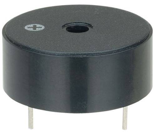
The program below plays a little tune on the piezo buzzer. It's
the same program as the Arduino Digital 'toneMelody' example but
only the used notes are defined for clarity.
The piezo is a passive device, in other words it needs to be
driven by a (square) wave at an appropriate frequency. The Arduino
tone() function handles this for us.
The piezo is fairly quiet (thankfully!). It is connected to D8. You will spot this in the code.
/*
  Melody

  Plays a melody

  created 21 Jan 2010
  modified 30 Aug 2011
  by Tom Igoe

  This example code is in the public domain.

  http://www.arduino.cc/en/Tutorial/Tone


  /*************************************************
   Public Constants
 *************************************************/

#define NOTE_G3  196
#define NOTE_A3  220
#define NOTE_B3  247
#define NOTE_C4  262

// notes in the melody:
int melody[] = {
  NOTE_C4, NOTE_G3, NOTE_G3, NOTE_A3, NOTE_G3, 0, NOTE_B3, NOTE_C4
};

// note durations: 4 = quarter note, 8 = eighth note, etc.:
int noteDurations[] = {
  4, 8, 8, 4, 4, 4, 4, 4
};

void setup() {
  // iterate over the notes of the melody:
  for (int thisNote = 0; thisNote < 8; thisNote++) {

    // to calculate the note duration, take one second
    // divided by the note type.
    //e.g. quarter note = 1000 / 4, eighth note = 1000/8, etc.
    int noteDuration = 1000 / noteDurations[thisNote];
    tone(D8, melody[thisNote], noteDuration);

    // to distinguish the notes, set a minimum time between them.
    // the note's duration + 30% seems to work well:
    int pauseBetweenNotes = noteDuration * 1.30;
    delay(pauseBetweenNotes);
    // stop the tone playing:
    noTone(D8);
  }
}

void loop() {
  // no need to repeat the melody.
}
// Open day demonstration
//-----------------------------------------------
// This code is designed for a ESP8266 device connected to a DHT11/22 temperature & humidity sensor
// The device is configured as an access point with a specific name
// Power up the device (plug it in!) and wait a few seconds
// Locate the 'new' wireless access point (Wemos web) which appears on your PC/laptop/tablet
// Join this network - no password required
// Go to http://192.168.4.1 in a web browser
// You should see the temperature & humidity from the DHT11/22. The page should refresh every 60 seconds
// Ian Sexton 2015
//-----------------------------------------------
#include <DHT.h>            //sensor library
#include <ESP8266WiFi.h>    //wifi library
#include <ESP8266WebServer.h> //server library

#define DHTPIN D5               //configure sensor connection pin
#define DHTTYPE DHT11         //& type
DHT dht(DHTPIN, DHTTYPE);

const char *ssid = "Wemos web";    //name of access point

ESP8266WebServer server(80);  //Go to http://192.168.4.1 in a web browser. Standard http port

//bits of a web page:
const String refresh = "<META HTTP-EQUIV=\"refresh\" CONTENT=\"60\">";  //reload after 60 seconds
// Pick a colour:
//const String format = "<body bgcolor=\"#cccccc\">"; //silver
//const String format = "<body bgcolor=\"#ccff99\">"; //pale green
//const String format = "<body bgcolor=\"#ffe6e6\">"; //pale pink
//const String format = "<body bgcolor=\"#ffffc2\">"; //pale yellow
const String format = "<body bgcolor=\"#ccffff\">";   //pale blue
// take a look at http://www.w3schools.com/tags/ref_colorpicker.asp for a full range of colours
const String h1 = "<h1>De Montfort University</h1>";    //heading 1
const String h2 = "<h2>Faculty of Technology</h2>";     //heading 2
//Put your name or something below
const String h3 = "<h2>Personalise it here</h2>";
const String msg1 = "We hope you enjoyed our Open Day, and continue to enjoy our gift to you.<br>";
const String msg2 = "This device measures temperature & relative humidity, the current values are:<br>";
//dynamic stuff inserted in here - see below
const String msg3 = "If you would like to know more about opportunities at DMU, please contact:<br><br>";
const String contact = "Joe Blogs<br>The Admissions Unit<br>DMU<br>The Gateway<br>blah<br>";
//I've deliberately separated this into parts to make it easier to modify

void setup()
{
  WiFi.softAP(ssid);          //start the access point
  server.on("/", webroot);    //we only have the root page
  server.begin();             //start the server
}

void loop()
{
  server.handleClient();
}

void webroot()
{
  float humidity = dht.readHumidity(); //read the sensor
  float temperature = dht.readTemperature();
  String webpage = refresh + format + h1 + h2 + h3 + msg1 + msg2; //build the webpage from parts above
  webpage += "<h2>Temperature: ";
  webpage += String(temperature);   //make it printable
  webpage += " C<br>";               //add the sensor readings in here
  webpage += "Humidity: ";
  webpage += String(humidity);      //make it printable
  webpage += " %<br></h2>";
  webpage += msg3 + contact;       //finish off the page - parts above too
  server.send(200, "text/html", webpage);  //and serve it...
}
The page served looks like this on my iPhone: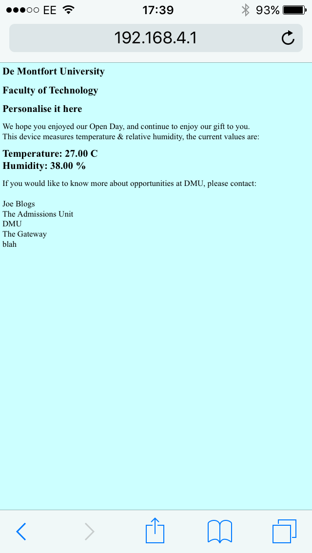
// Connect to a WiFi network
#include <ESP8266WiFi.h>
//const char* ssid = "mynetwork"; //c method
//const char* password = "mypassword";
String ssid = "mynetwork"; //c++ method
String password = "mypassword";
void setup()
{
Serial.begin(115200);
//WiFi.begin(ssid, password); //c method
WiFi.begin(ssid.c_str(), password.c_str()); //c++ method
Serial.println();
// Wait for connection - this could keep trying forever
while (WiFi.status() != WL_CONNECTED) //meaning: not equal to 'wireless connected'
{
delay(500);
Serial.print("."); //progress bar
}
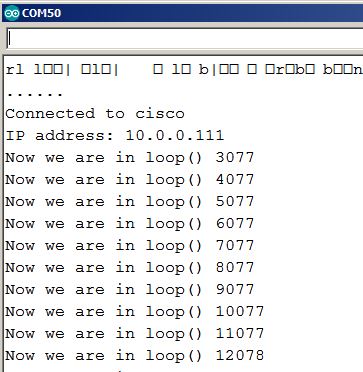
Serial.print("\r\nConnected to ");
Serial.println(ssid);
Serial.print("IP address: ");
Serial.println(WiFi.localIP()); //IP address 'given' from access point.
}
void loop()
{
Serial.print("Now we are in loop() ");
Serial.println(millis()); //so that we can see the program is running
delay(1000); //we'd usually do something useful now, eg serve web pages
}
Here we connect to an existing WiFi network and the device can be
accessed from anywhere on the same network. You need to use your network credentials for ssid & password.
#include <ESP8266WiFi.h>
#include <ESP8266WebServer.h>

#define LED D0

const char* ssid = "mynetwork";
const char* password = "mypassword";

ESP8266WebServer server(80);

void setup(void) {
  pinMode(LED, OUTPUT);
  digitalWrite(LED, 0);
  Serial.begin(115200);
  WiFi.begin(ssid, password);
  Serial.println("\r\nConnecting");

  // Wait for connection
  while (WiFi.status() != WL_CONNECTED) {
    delay(500);
    Serial.print(".");
  }
  Serial.print("\r\nConnected to ");
  Serial.println(ssid);
  Serial.print("IP address: ");
  Serial.println(WiFi.localIP());

  server.on("/", handleRoot);
  server.begin();
  Serial.println("HTTP server started");
}

void loop(void) {
  server.handleClient();
}

void handleRoot() {
  digitalWrite(LED, 1);
  server.send(200, "text/plain", "Hello from your Wemos board!");
  digitalWrite(LED, 0);
}
This example is very like the previous (AP) example. The web page
delivered is much simpler & the LED on our board flashes when a
request is made./* Create a WiFi access point and provide a web server on it.
This program uses SPIFFS to hold files
Simply create a website and upload to SPIFFS
The root is 'index.htm'
Use relative links so you can check your website before uploading
Use the 'ESP8266 Sketch Data Upload' from 'Tools' menu in Arduino IDE
AFTER putting your files in 'data' folder in the sketch folder
*/
#include <ESP8266WiFi.h>
#include <ESP8266WebServer.h>
#include <FS.h>
const char *ssid = "Wemos_SPIFFS";
const char *password = ""; //no password
ESP8266WebServer server(80); //port 80
//-----------------------------------------------------------------------------------------
void setup() {
Serial.begin(115200);
SPIFFS.begin();
Serial.println();
Serial.print("Configuring access point...");
WiFi.softAP(ssid, password);
IPAddress myIP = WiFi.softAPIP();
Serial.print("Access Point IP address: ");
Serial.println(myIP);
server.onNotFound(handleOther);
server.begin();
Serial.println("HTTP server started");
}
//-----------------------------------------------------------------------------------------
void loop() {
server.handleClient();
}
//-----------------------------------------------------------------------------------------
//tell the client what to do with data
bool loadFromSpiffs(String path)
{
String dataType = "text/plain";
if (path.endsWith("/")) path += "index.htm"; //this is where index.htm is created
if (path.endsWith(".src")) path = path.substring(0, path.lastIndexOf("."));
else if (path.endsWith(".htm")) dataType = "text/html";
else if (path.endsWith(".css")) dataType = "text/css";
else if (path.endsWith(".js")) dataType = "application/javascript";
else if (path.endsWith(".png")) dataType = "image/png";
else if (path.endsWith(".gif")) dataType = "image/gif";
else if (path.endsWith(".jpg")) dataType = "image/jpeg";
else if (path.endsWith(".ico")) dataType = "image/x-icon";
else if (path.endsWith(".xml")) dataType = "text/xml";
else if (path.endsWith(".pdf")) dataType = "application/pdf";
else if (path.endsWith(".zip")) dataType = "application/zip";
File dataFile = SPIFFS.open(path.c_str(), "r"); //open file to read
if (!dataFile) //unsuccesful open
{
Serial.print("Don't know this command and it's not a file in SPIFFS : ");
Serial.println(path);
return false;
}
if (server.hasArg("download")) dataType = "application/octet-stream";
if (server.streamFile(dataFile, dataType) != dataFile.size()) {} //a lot happening here
dataFile.close();
return true; //shouldn't always return true, Added false above
}
//-----------------------------------------------------------------------------------------
void handleOther() {
if (loadFromSpiffs(server.uri())) return; //gotcha - it's a file in SPIFFS
String message = "Not Found\n\n"; //or not...
message += "URI: "; //make a 404 response & provide debug information
message += server.uri();
message += "\nMethod: ";
message += (server.method() == HTTP_GET) ? "GET" : "POST";
message += "\nArguments: ";
message += server.args();
message += "\n";
for (uint8_t i = 0; i < server.args(); i++)
{
message += " NAME:" + server.argName(i) + "\n VALUE:" + server.arg(i) + "\n";
}
server.send(404, "text/plain", message);
Serial.println(message);
}
A potential issue with this approach is that it doen't lend itself well to the use of 'live' data. The program above simply spools a web page which is stored in SPIFFS. Generally, we want to display things like sensor readings which obviously are not known when the SPIFFS page is created. There are a few ways around this. Possibly the simplest is to use a bit of Javascript. A small Javascript routine can be embedded in the SPIFFS page, it will make a 'GET' request & our server can return html formatted data. I have another page which illustrates this concept.OTA (Over The Air) programming is a bonus feature which comes from having WiFi. Usually it's not a problem to connect your board to your PC with a USB cable, but there are plenty of instances when this isn't great. Your board might be miles away. It might be inconvenient to access physically. It could be connected to hazardous voltages etc.
I can remember the day when my iPhone needed connecting to my PC to perform updates. How ridiculous! My TV occasionally needs updates, thankfully it uses OTA as it's at the opposite end of the house to my PC!
The ESP8266 at the heart of our board can perform OTA programming a few different ways & these are all well explained in the documentation.
The key thing to remember is that this facility is not automatic! It's up to you to set it up!
This might sound obvious until you trip up... The program below does very little, it connects to your WiFi and flashes the LED. When you run this program your device is ready for OTA programming. If you look at Tools>Port in the Arduino IDE you should see that a network port is available (restart the IDE if there is nothing there).
Select the network port shown & program the device again with the same code, maybe change the rate the LED blinks just for proof that it works. Your program should load at lightning speed & run!
BUT if you load any other program from this page it will kill the OTA capability. Those lines which say, 'MUST be included in ALL programs.' Mean exactly that. Miss them out & you kill the OTA capability. This is very easy to do accidentally!
Imagine you are working with a BMP180 or some other I2C device. Your program uses OTA, you've uploaded it a dozen times with OTA but the I2C device refuses to work... So you upload the I2C scanner shown above & it tells you that you have the wrong address...
That's great to know, but you've just killed the OTA because the I2C scanner doesn't include the facility... Be careful!
Another potential issue is poor management. You may have a lot of devices on your network which are set up for OTA programming. Be sure to program the right one!
The moral of the story: OTA is extremely useful but don't be surprised if/when it bites your bum!
This topic is explained well in the documentation. Read it.
// OTA (Over The Air) programming
// this is a minimal example to show how it's done
// Ian Sexton 2016

#include <ESP8266WiFi.h>
#include <ArduinoOTA.h>   //MUST be included in ALL programs

#define LED D0

const char* ssid = "your_network";
const char* password = "your_password";

void setup()
{ //standard connect as station stuff
  pinMode(LED, OUTPUT);
  Serial.begin(115200);
  Serial.println("\r\nBooting");
  WiFi.mode(WIFI_STA);
  WiFi.begin(ssid, password);
  while (WiFi.waitForConnectResult() != WL_CONNECTED)
  {
    Serial.println("\r\nConnection Failed! Rebooting...");
    delay(5000);
    ESP.restart();
  }
  ArduinoOTA.begin();    //MUST be included in ALL programs
}

void loop()
{
  ArduinoOTA.handle();   //MUST be included in ALL programs
  digitalWrite(LED, !digitalRead(LED));   //blink to show life
  delay(500);

}
A sad fact of life is that WiFi (IEEE802.11) is not low power. The ESP8266 chip in our board can take up to 300mA of current. If we were to try running a device from batteries they wouldn't last very long (unless they were extremely large!). To put this in context, a typical rechargeable AA cell might have a capacity of around 2000mAH.
A battery pack made up of such cells might power a device for around 6 hours. That might be sufficient in some applications, it might not in others.
Many of the examples we have used so far concern reading of sensors. We might make the data available on a simple webserver. This approach means that our device is doing very little apart from when a client connects and requests the data.
If we approach the problem from another angle we can save enormous amounts of power & provide considerably extended battery life.
It is important to note from the outset that our Wemos board was never designed to be a true low power device and the best we can do here is to illustrate what can be done.
To implement a low power scheme we put the device to sleep (which uses less power). It wakes periodically, does something useful, and then returns to sleep.
This doesn't fit with our idea of presenting the data, on demand, via a web server. If our device is asleep it can't be checking for requests at the same time, however it might wake, send the data somewhere and then go back to sleep. Suppose we want to monitor the temperature in our living room. How often do we need to measure it? This will probably depend on why we are monitoring the temperature, but for the sake of illustration let's say we need to take a fresh reading every ten minutes. So we can sleep for ten minutes, wake, read the temperature, send the data somewhere, and sleep for another ten minutes. When the ESP8266 is in 'deep sleep' it requires around 20uA of current. At this rate our 2000mAH battery would last 100,000 hours or around 11 years. If it wakes every 10 minutes to do its stuff this obviously has an impact, but it only needs to be awake for a few seconds. I'm sure you get the idea!
As indicated, our board isn't designed for low power. The ESP8266 isn't the only device on our board which uses power. There is a USB to serial chip on the Wemos board, our sensors are wired to be permanently 'on', the pot is wired as a potential divider, we use LEDs without any care etc. The lowest current we can hope for on our board is around 40-50mA if we make the ESP8266 sleep.
Putting it to sleep is simple. We use a function: ESP.deepSleep(microseconds);
Waking it is a little more tricky and we need to use a hardware modification to reset the ESP8266 when it's time to wake up. The Wemos pin D0 goes low at the end of a sleep and by connecting this pin to the RST (reset) pin our board is woken with a reset at the end of the sleep time. Unfortunately that's not the end of the story, the Wemos board also uses the RST pin to start the serial bootloader so we have a conflict. If we connect a diode (preferably Schottky) between D0 & RST this will allow the RST or the bootloader to operate. The cathode of the diode should be connected to D0, anode to RST. I'm told that a resistor (~1k) between the pins will also work but I've not tried it. Also note that we use D0 to drive the white LED in normal use. This is out of bounds if you want to try sleeping!
The program below demonstrates deep sleep. It doesn't do anything clever but it can be instructive. Low power operation is almost an entire subect in itself but an overview is useful.
There are quite a few articles on the web which cover this topic but I don't know of anything definitive. This one is worth a read.
// deep sleep example
// D0 must be connected to RST on the Wemos board
// The best way to do this is to connect a Schottky diode between the pins
// with the cathode to D0, anode to RST.
// WiFi is switched on to make current measurements more realistic
// Ian Sexton 2017

#include <ESP8266WiFi.h>

#define buzzer D8
#define sleepSeconds 20   //Esp.deepSleep() expects microseconds
const char* ssid = "esp";

void setup() {
  Serial.begin(115200);
  tone(buzzer,1500,200); //beep the buzzer on waking
  Serial.println("\n\nRunning for 20 seconds");
  WiFi.softAP(ssid);          //start the access point
  delay(20000);               // stay awake for a while
  Serial.println("\n\nOff to sleep now\n");
  ESP.deepSleep(sleepSeconds * 1000000);  //time for bed
}

void loop() {
}
-----------------------------------------------------------------------------------------------------------------------------------------------------
In an earlier example we used a DHT11 temperature & humidity sensor to create a web page. This is great fun but it isn't very practical. Install two or three of these sensors & you are faced with two or three web servers, each having different IP addresses. Put one in every room in the house & we could easily be in double figures. Apart from sensors, we might have actuators, eg we might want to control AC mains outlets &/or lighting in every room. It's not difficult to imagine that a truly 'smart' home could have 100+ devices competing for your attention.
Returning to our DHT11 example: Imagine it is telling you that your living room temperature is 27C in the middle of winter. You are on holiday & forgot to alter the heating - no problem, you can change the heating remotely. Then you notice that your house lights are all off 24/7. You can fix that remotely too.
You can work your way through all of the sensors & actuators. You will need another holiday when you are through!
Wouldn't it be useful if our devices could talk to each other? We could program one device as a client and another as a server. We could potentially produce a mesh network where data could be shared across the network.
Or we could use MQTT! It's beyond our scope here to provide a detailed explanation of MQTT, for which you are referred to the literature.
Shamelessly lifted from the literature: Essentially, MQTT is a Client Server publish/subscribe messaging transport protocol.
It is light weight, open, simple, and designed so as to be easy to
implement. These characteristics make it ideal for use in many
situations, including constrained environments such as for communication
in Machine to Machine (M2M) and Internet of Things (IoT) contexts where
a small code footprint is required and/or network bandwidth is at a
premium.
Think of it like a Facebook for micros. You can post messages, others can see them. You can also see stuff that you are interested in. Your dialogue with other users (clients) is mediated by Facebook (server). So the MQTT server sits in the middle of all the devices/clients and manages the communication between them. Traditionally the MQTT server was referred to as a 'broker' but this seems to have given way to 'server' in the current terminology.
A problem for us is that there are several Arduino/ESP8266 MQTT (client) libraries available.
The program below uses the original Arduino library written by Nick O'Leary of IBM who created MQTT. The code is slightly modified from the ESP8266 example in the library.
We will see why later.
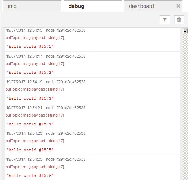
What does this program do? It publishes a message, 'hello world' to the topic called 'outTopic' and it subscribes to a topic called 'inTopic' which hopefully tells us what to do with the LED.
/*
  Basic ESP8266 MQTT example

  This sketch demonstrates the capabilities of the pubsub library in combination
  with the ESP8266 board/library.

  It connects to an MQTT server then:
  - publishes "hello world" to the topic "outTopic" every two seconds
  - subscribes to the topic "inTopic", printing out any messages
    it receives. NB - it assumes the received payloads are strings not binary


  It will reconnect to the server if the connection is lost using a blocking
  reconnect function. See the 'mqtt_reconnect_nonblocking' example for how to
  achieve the same result without blocking the main loop.

  To install the ESP8266 board, (using Arduino 1.6.4+):
  - Add the following 3rd party board manager under "File -> Preferences -> Additional Boards Manager URLs":
       http://arduino.esp8266.com/stable/package_esp8266com_index.json
  - Open the "Tools -> Board -> Board Manager" and click install for the ESP8266"
  - Select your ESP8266 in "Tools -> Board"

*/
#define LED D0
#include <ESP8266WiFi.h>
#include <PubSubClient.h>

// Update these with values suitable for your network.

const char* ssid = "your_network";
const char* password = "your_password";
const char* mqtt_server = "10.0.0.101"; //IP address of YOUR server/broker

WiFiClient espClient;
PubSubClient client(espClient);
long lastMsg = 0;
char msg[50];
int value = 0;

void setup() {
  pinMode(LED, OUTPUT);     // Initialize the LED pin as an output
  Serial.begin(115200);
  setup_wifi();
  client.setServer(mqtt_server, 1883);
  client.setCallback(callback);
}

void setup_wifi() {

  delay(10);
  // We start by connecting to a WiFi network
  Serial.println();
  Serial.print("Connecting to ");
  Serial.println(ssid);

  WiFi.begin(ssid, password);

  while (WiFi.status() != WL_CONNECTED) {
    delay(500);
    Serial.print(".");
  }

  Serial.println("");
  Serial.println("WiFi connected");
  Serial.println("IP address: ");
  Serial.println(WiFi.localIP());
}

void callback(char* topic, byte* payload, unsigned int length) {
  String message;
  Serial.print("Message arrived [");
  Serial.print(topic);
  Serial.print("] ");
  for (int i = 0; i < length; i++) {
    Serial.print((char)payload[i]);
    message += ((char)payload[i]);  //turn payload into string - easier to understand
  }
  Serial.println();

// act on a received message from the server
  if (message == "on")
    digitalWrite(LED, HIGH);   // Turn the LED on
  if (message == "off")
    digitalWrite(LED, LOW);   // Turn the LED off
  if (message == "toggle")
    digitalWrite(LED, !digitalRead(LED));  // Toggle the LED

}

void reconnect() {
  // Loop until we're reconnected
  while (!client.connected()) {
    Serial.print("Attempting MQTT connection...");
    // Attempt to connect
    if (client.connect("ESP8266Client")) {
      Serial.println("connected");
      // Once connected, publish an announcement...
      client.publish("outTopic", "hello world");
      // ... and resubscribe
      client.subscribe("inTopic");
    } else {
      Serial.print("failed, rc=");
      Serial.print(client.state());
      Serial.println(" try again in 5 seconds");
      // Wait 5 seconds before retrying
      delay(5000);
    }
  }
}
void loop() {

  if (!client.connected()) {
    reconnect();
  }
  client.loop();

  long now = millis();
  if (now - lastMsg > 2000) {
    lastMsg = now;
    ++value;
    snprintf (msg, 75, "hello world #%ld", value);
    Serial.print("Publish message: ");
    Serial.println(msg);
    client.publish("outTopic", msg);
  }
}
It's faintly absurd to dedicate so few lines here to such an enormous topic but it's useful to provide a very brief introduction.
The example above requires the existence of a MQTT server/broker. Although there is such a server available for the ESP8266 platform we would generally use a more powerful device. The Raspberry Pi is very often used for this role. You don't actually need your own server at all. There are quite a few freely available MQTT servers on the interweb.
I prefer to keep things local. I use a rPi but tend to use a PC for development work. This is quicker & simpler
MQTT suddenly becomes more interesting with Node-Red!
If you want to use a rPi it's quite simple & is included with recent releases of the firmware. An even simpler route is to use The Thingbox which is a pre-configured SD card image with Node-Red & MQTT ready to go.
Installing Node-Red on a PC is a little more complex. I recommend you follow this video.
You also need to install the Mosquitto MQTT server if you want to work on a PC. The easiest way to do this is to download this zip file. Unzip the file & copy to a convenient location on your PC. Start the server by double clicking the file 'mosquitto.exe' contained in the folder.
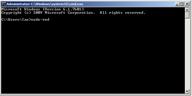
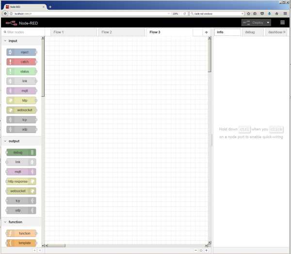
Start Node-Red by opening a command window & typing 'node-red'
Now open a web browser and enter 'localhost:1880' in the address bar. You should see something like this:
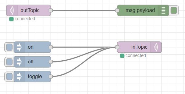
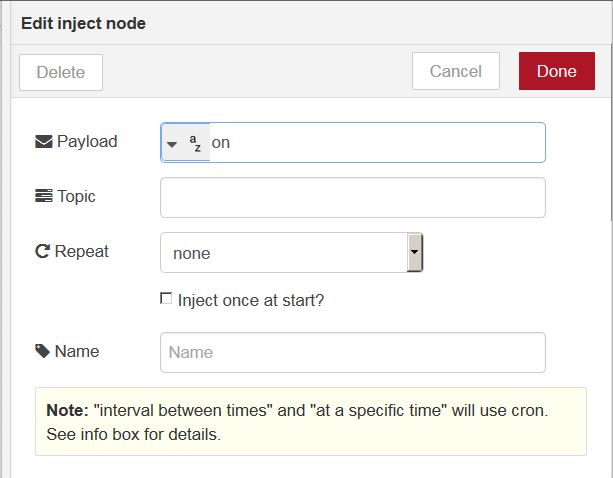
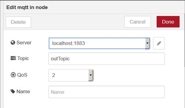
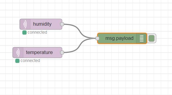
Let's create our first flow. Drag & drop the following nodes from the panel on the left:
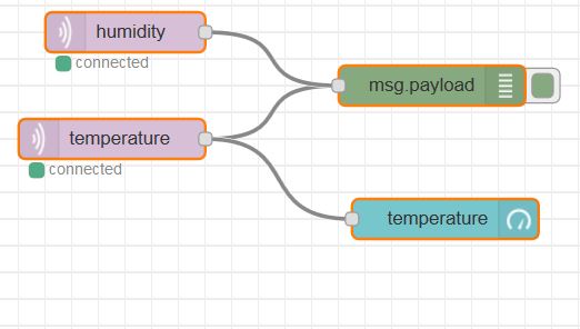
Connect the nodes like this: